- 您现在的位置:买卖IC网 > Sheet目录509 > SI3867DV-T1-GE3 (Vishay Siliconix)MOSFET P-CH 20V 3.9A 6-TSOP
AN823
Vishay Siliconix
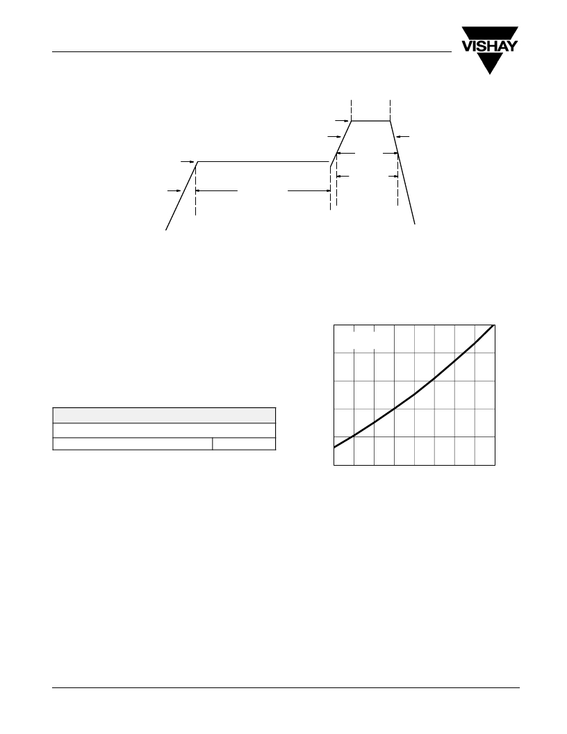
10 s (max)
255 ? 260 _ C
140 ? 170 _ C
1 X 4 _ C/s (max)
217 _ C
60 s (max)
3-6 _ C/s (max)
3 _ C/s (max)
60-120 s (min)
Reflow Zone
Pre-Heating Zone
Maximum peak temperature at 240 _ C is allowed.
FIGURE 3. Solder Reflow Temperature and Time Durations
THERMAL PERFORMANCE
A basic measure of a device’s thermal performance is the
On-Resistance vs. Junction Temperature
junction-to-case thermal resistance, R q jc , or the
junction-to-foot thermal resistance, R q jf . This parameter is
measured for the device mounted to an infinite heat sink and
is therefore a characterization of the device only, in other
words, independent of the properties of the object to which the
device is mounted. Table 1 shows the thermal performance
of the TSOP-6.
TABLE 1.
Equivalent Steady State Performance—TSOP-6
Thermal Resistance R q jf 30 _ C/W
1.6
1.4
1.2
1.0
0.8
0.6
V GS = 4.5 V
I D = 6.1 A
? 50
? 25
0
25
50
75
100
125
150
SYSTEM AND ELECTRICAL IMPACT OF
TSOP-6
In any design, one must take into account the change in
MOSFET r DS(on) with temperature (Figure 4).
www.vishay.com
2
T J ? Junction Temperature ( _ C)
FIGURE 4. Si3434DV
Document Number: 71743
27-Feb-04
发布紧急采购,3分钟左右您将得到回复。
相关PDF资料
SI3905DV-T1-GE3
MOSFET P-CH D-S 8V 6-TSOP
SI3909DV-T1-GE3
MOSFET 2P-CH 20V 6TSOP
SI3911DV-T1-GE3
MOSFET P-CH DUAL 20V 6TSOP
SI3981DV-T1-GE3
MOSFET P-CH DUAL 20V 6-TSOP
SI3983DV-T1-GE3
MOSFET P-CH DUAL 20V 6-TSOP
SI4056DY-T1-GE3
MOSFET N-CH 100V D-S 8SOIC
SI4100DY-T1-E3
MOSFET N-CH D-S 100V 8-SOIC
SI4104DY-T1-E3
MOSFET N-CH D-S 100V 8-SOIC
相关代理商/技术参数
SI3872DV-T1
功能描述:MOSFET 30/-20V RoHS:否 制造商:STMicroelectronics 晶体管极性:N-Channel 汲极/源极击穿电压:650 V 闸/源击穿电压:25 V 漏极连续电流:130 A 电阻汲极/源极 RDS(导通):0.014 Ohms 配置:Single 最大工作温度: 安装风格:Through Hole 封装 / 箱体:Max247 封装:Tube
SI3872DV-T1-E3
功能描述:MOSFET 30/-20V RoHS:否 制造商:STMicroelectronics 晶体管极性:N-Channel 汲极/源极击穿电压:650 V 闸/源击穿电压:25 V 漏极连续电流:130 A 电阻汲极/源极 RDS(导通):0.014 Ohms 配置:Single 最大工作温度: 安装风格:Through Hole 封装 / 箱体:Max247 封装:Tube
SI3879DV
制造商:VISHAY 制造商全称:Vishay Siliconix 功能描述:P-Channel 20-V (D-S) MOSFET with Schottky Diode
SI3879DV-T1-E3
功能描述:MOSFET 20V 5.0A 3.3W RoHS:否 制造商:STMicroelectronics 晶体管极性:N-Channel 汲极/源极击穿电压:650 V 闸/源击穿电压:25 V 漏极连续电流:130 A 电阻汲极/源极 RDS(导通):0.014 Ohms 配置:Single 最大工作温度: 安装风格:Through Hole 封装 / 箱体:Max247 封装:Tube
SI3879DV-T1-GE3
功能描述:MOSFET 20V 5.0A 3.3W 70mohm @ 4.5V RoHS:否 制造商:STMicroelectronics 晶体管极性:N-Channel 汲极/源极击穿电压:650 V 闸/源击穿电压:25 V 漏极连续电流:130 A 电阻汲极/源极 RDS(导通):0.014 Ohms 配置:Single 最大工作温度: 安装风格:Through Hole 封装 / 箱体:Max247 封装:Tube
SI3900DV
制造商:Vishay Intertechnologies 功能描述:DUAL N CHANNEL MOSFET, 20V, 2.4A, Transistor Polarity:N Channel, Continuous Drai 制造商:Vishay Siliconix 功能描述:DUAL N CHANNEL MOSFET, 20V, 2.4A, Transistor Polarity:N Channel, Continuous Drain Current Id:2.4A, Drain Source Voltage Vds:20V, On Resistance Rds(on):125mohm, Rds(on) Test Voltage Vgs:4.5V, Threshold Voltage Vgs:1.5V, No. of Pins:6 , RoHS Compliant: Yes
SI3900DV_08
制造商:VISHAY 制造商全称:Vishay Siliconix 功能描述:Dual N-Channel 20-V (D-S) MOSFET
SI3900DV_09
制造商:VISHAY 制造商全称:Vishay Siliconix 功能描述:Dual N-Channel 20-V (D-S) MOSFET
